WhatsApp
Cart is empty

Victron Energy BatteryProtect 12/24V-65A
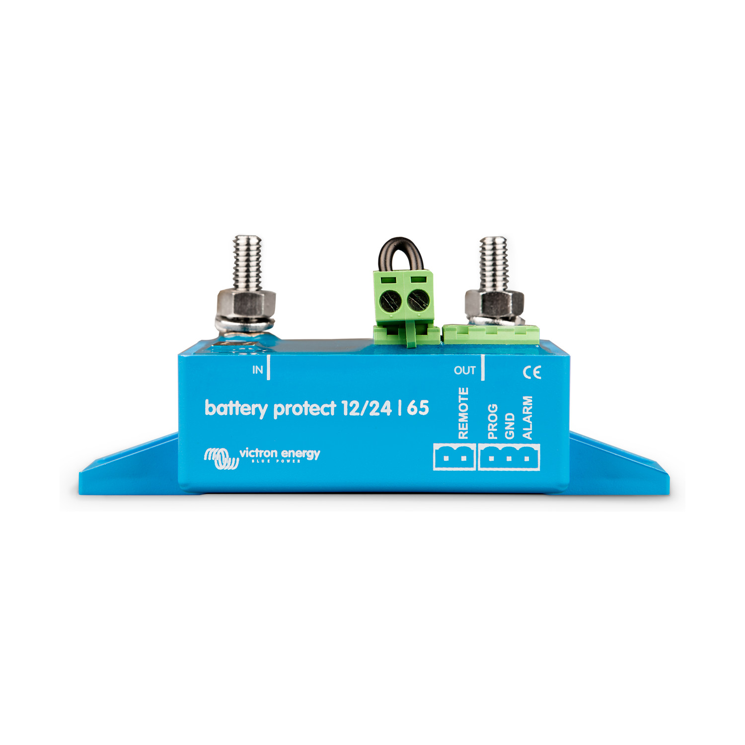
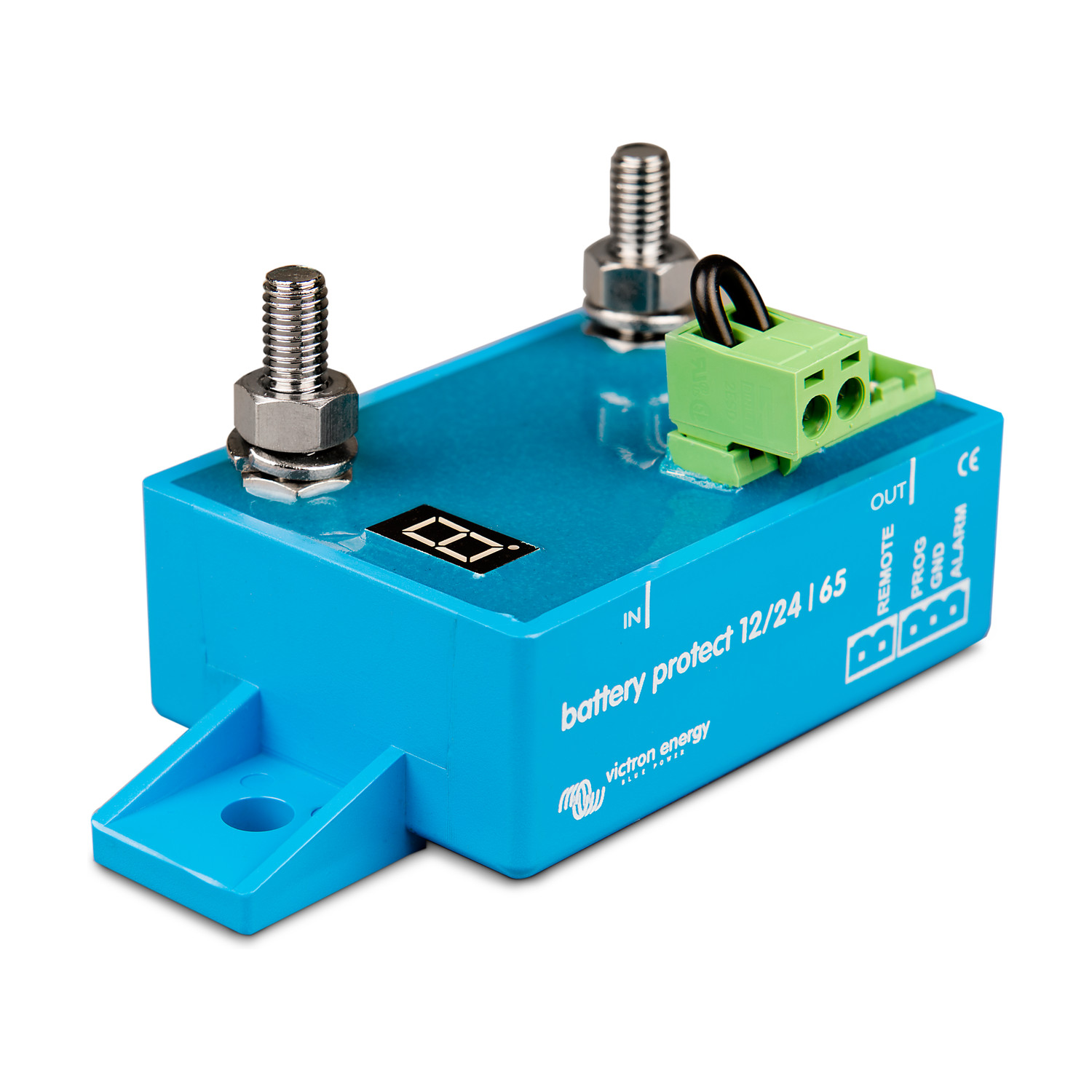



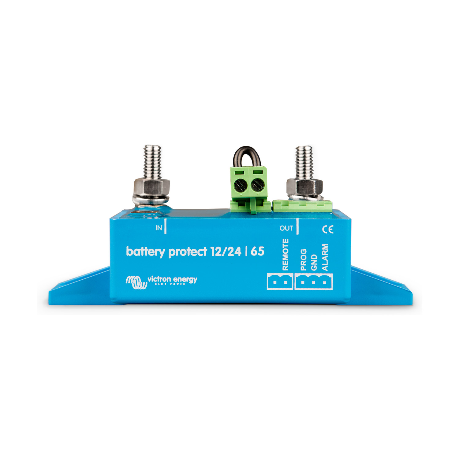 The Victron Energy BatteryProtect 12/24V-65A disconnects non-essential DC loads before the battery is deeply discharged, which would damage it, or before too little charge remains to start the engine. It is a uni-directional MOSFET switch in the positive cable: current can only flow from the IN (battery) terminal to the OUT (load) terminal.
12/24 V auto-ranging. The 12/24 V models detect the system voltage once, at first power-up, and store it. Disconnect and reconnect thresholds are then set on the seven-segment display by connecting the PROG pin to the GND pin. The factory defaults are 10.5 V or 21 V to disconnect and 12 V or 24 V to reconnect.
Timed alarm and disconnect. If the battery stays below the disconnect threshold for 12 seconds, the alarm output (maximum 50 mA) is activated. The load is disconnected 90 seconds later, unless the voltage has already recovered — for example after the engine has been started. The load is reconnected 30 seconds after the voltage rises above the reconnect threshold. On the 12/24 V models the load is also disconnected if the voltage exceeds 16 V or 32 V.
Lithium batteries and chargers. A Li-ion mode lets an external BMS, such as a VE.Bus BMS or a Lynx Smart BMS ATD/ATC contact, control the unit through the remote terminal, with immediate disconnect. The same device can sit between a charger and a lithium battery to interrupt charge, but only if it is oriented so that current still flows from IN to OUT. It is not designed for reverse currents from charging sources. The DC input of an inverter or inverter/charger must never be wired through a BatteryProtect; use the inverter's remote port instead.
This is the non-Smart BatteryProtect family, programmed from the seven-segment display. A separate Smart BatteryProtect family adds Bluetooth and VictronConnect and uses different part numbers.
Features
- MOSFET switching with no relay contacts, so the unit does not produce sparks
- This default model is rated at 65 A continuous and 250 A peak for 30 seconds; the 100 A, 220 A and 48 V-100 A versions are in the Models & part numbers table
- Current consumption on the 12/24 V models is 1.5 mA when on and 0.6 mA when off or after a low-voltage shutdown (2.0 mA / 1.5 mA on the 48 V-100 A)
- Electronics are potted to IP67; the connections are IP00
- Remote on/off terminal and a short-circuit-proof alarm output
- A connector with a preassembled DC minus cable is included
Models & part numbers
| Model | Part number | Continuous current | Peak current (30 s) | Operating voltage | Connection |
| BatteryProtect 12/24V-65A | BPR000065400 | 65 A | 250 A | 6–35 V | M6 |
| BatteryProtect 12/24V-100A | BPR000100400 | 100 A | 600 A | 6–35 V | M8 |
| BatteryProtect 12/24V-220A | BPR000220400 | 220 A | 600 A | 6–35 V | M8 |
| BatteryProtect 48V-100A | BPR048100400 | 100 A | 250 A | 24–64 V | M8 |
Fitting
Install the unit in a well-ventilated place, preferably close to the battery (no more than 50 cm away) and not above it, where corrosive gases can collect. Use cable of a suitable size and length for the load: a long or undersized positive cable can cause a short-circuit alarm at start-up or an unexpected shutdown.
Fit a correctly sized fuse in the cable between the battery and the BatteryProtect, as required by local rules. Connect the supplied 1.5 mm² earth wire only to the battery negative (or the vehicle chassis), with a 300 mA fuse in that wire; do not share it with other equipment. Observe the IN to OUT orientation. Do not connect the load until programming is complete. The 12/24 V models store the detected system voltage after the first power-up; use program d on the display if the unit is later moved to a system of the other voltage.
Tighten the main connections to 5 Nm on the 65 A model (M6) and to 9 Nm on the 100 A, 220 A and 48 V-100 A models (M8). A remote on/off switch can be wired to the two-pin remote terminal, or the REMOTE pin can be taken high to battery positive. Under no circumstances should the DC input of an inverter or inverter/charger be taken through a BatteryProtect; if you need to control one, use its remote port.
Maintenance
There are no user-serviceable parts inside the potted electronics. Keep the IP00 connections clean and dry, and periodically check that the studs remain tight to the torque figures above and that the battery fuse is of the correct rating.
FAQ
Can it carry charging current in both directions? No. The BatteryProtect is uni-directional. Current may only flow from IN to OUT, and it is not designed for reverse currents from charging sources. If you use one to interrupt a charger, turn the unit so that the charger is on the IN side and the battery on the OUT side. Two units are needed if both load disconnect and charger disconnect are required.
Can I place it in the DC feed to an inverter? No. Connecting an inverter or inverter/charger to the BatteryProtect through its DC input is not permitted and can damage the unit, because a reverse current may flow and because the inrush can trip the short-circuit protection. Use the BatteryProtect to control the inverter's remote on/off port instead.
How do I set the disconnect voltage? On this non-Smart family the seven-segment display is programmed by connecting the PROG pin to the GND pin. The display steps through shutdown and restart pairs (0–9) and then through operating modes, including buzzer or LED (A), relay (b), lithium (C) and system-voltage detect (d). Do not connect the load output until programming is finished. The full table is in the official manual.
How does this differ from the Smart BatteryProtect? The Smart family is a separate range with different part numbers. It adds Bluetooth and programming through VictronConnect. This family is set from the seven-segment display and the PROG pin only.
Specifications
| 12/24V-65A | 12/24V-100A | 12/24V-220A | 48V-100A | |
| Max. continuous load current | 65 A | 100 A | 220 A | 100 A |
| Peak current (30 seconds) | 250 A | 600 A | 600 A | 250 A |
| Operating voltage range | 6–35 V | 24–64 V | ||
| Current consumption (on / off) | 1.5 mA / 0.6 mA | 2.0 mA / 1.5 mA | ||
| Alarm output delay | 12 seconds | |||
| Maximum load on alarm output | 50 mA (short-circuit proof) | |||
| Load disconnect delay | 90 seconds (immediate if triggered by a VE.Bus BMS) | |||
| Load reconnect delay | 30 seconds | |||
| Default thresholds (disconnect / reconnect) | 10.5 V or 21 V / 12 V or 24 V | 42 V / 48 V | ||
| Over-voltage disconnect | 16 V or 32 V | 64 V | ||
| Operating temperature | Full load: −40 °C to +40 °C (up to 60 % of nominal load at 50 °C) | |||
| IP rating | Electronics: IP67 (potted); connections: IP00 | |||
| Connection / mounting torque | M6 / 5 Nm | M8 / 9 Nm | M8 / 9 Nm | M8 / 9 Nm |
| Weight (product) | 0.2 kg | 0.5 kg | 0.8 kg | 0.8 kg |
| Dimensions (h × w × d) | 40 × 48 × 106 mm | 59 × 42 × 115 mm | 62 × 123 × 120 mm | 62 × 123 × 120 mm |
The BatteryProtect is not designed for reverse currents from charging sources. Official specifications: Victron Energy datasheets for BatteryProtect 12/24V 65A/100A/220A and BatteryProtect 48V-100A, and the February 2025 (rev 05) manuals.
Included
- BatteryProtect unit
- Connector with preassembled DC minus cable (1.5 mm²), for the GND connection
Optional Accessories
A correctly sized fuse must be fitted in the positive cable between the battery and the BatteryProtect. These are fuse types we list in the same electrical range; choose the rating to suit the cable and the model.
| Code | BatteryProtect | Availability | Price | |
|---|---|---|---|---|

|
VICTRON ENERGY BPR000065400
|
7 days
|
€37.99 (€31.40 ex. VAT) |
No posts found